Preparing to set up a vehicle inspection line

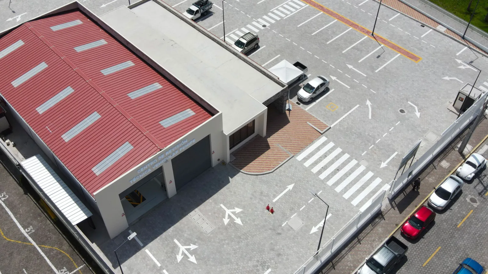
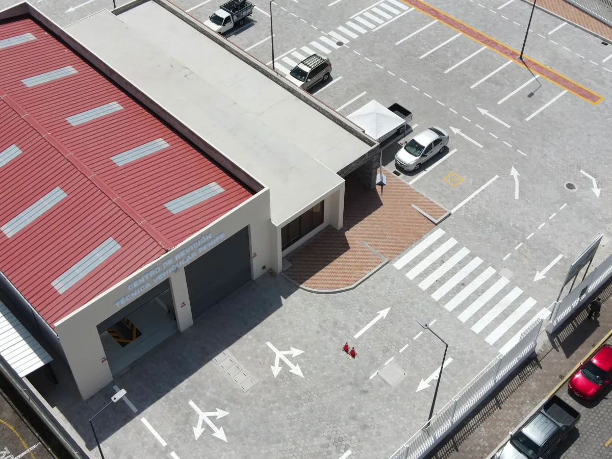
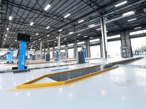
Before installing a vehicle inspection line, the facility must be assessed: dimensions, flooring, access, utilities, and traffic flow. Here is the information to gather and the constraints to verify to ensure that the installation is feasible—and sustainable in practice.

Implanter un centre de contrôle technique

Survey the premises

A layout study begins with a survey, not with a plan. The elements below determine the feasible configurations: until they are known, no layout can be approved.

  • Usable dimensions: length, width, clear height to the ceiling and clearance under any obstacles (beams, utility lines, sectional doors).
  • The nature and condition of the floor: type of slab, thickness, load-bearing capacity, presence of an existing pit or foundation.
  • Access points: width and height of openings, available turning radius at the entrance and exit, possible direction of traffic.
  • Utilities: available electrical power and location of the electrical panel, compressed air, drainage, and IT network.
  • Building constraints: columns, slopes, thresholds, areas where construction is not permitted, shared walls.

From Design to Installation

01

Survey and dimensioned drawing

The facility is surveyed and mapped, including its constraints and utility systems.

02

Proposed layout

A suggested workstation layout is provided based on the selected equipment configuration.

03

Website Preparation

Civil engineering, connections, and networks are handled according to the provided requirements.

04

Delivery and Installation

The equipment is delivered to a site ready to receive it, then installed and commissioned.

Organize traffic flow before placing the stations

The most costly mistake in layout planning is positioning the equipment first and then trying to figure out the traffic flow. It is the opposite approach that results in a smooth-running facility: first define the vehicle’s path—entry, successive stations, exit—then place the equipment along that path.

This path must remain passable under actual operating conditions: a vehicle waiting, an operator moving about, an open door. Points to consider:

  • Is traffic through traffic (opposite entry and exit) or reverse traffic? The former improves traffic flow but requires two openings.
  • Where is the waiting area for vehicles located—inside or in the parking lot?
  • What is the work area around each station, particularly around the brake test bench and the headlight adjustment area?
  • Where are the data entry station and reception area located in relation to the line?

Check the specific requirements for each piece of equipment

Each equipment family has its own building requirements. The exact prerequisites depend on the selected model and will be confirmed during the planning phase.

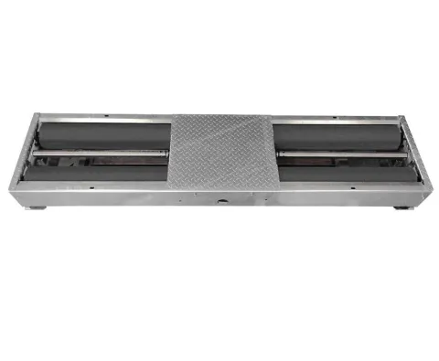
Brake dynamometer

This is the most space-intensive equipment for the facility. Depending on the chosen configuration—recessed into a concrete foundation or surface-mounted with access ramps—the installation work, space requirements, and accessibility differ significantly. The approach length upstream and downstream must be sufficient to allow the vehicle to be positioned straight.

See the brake test stands product line.

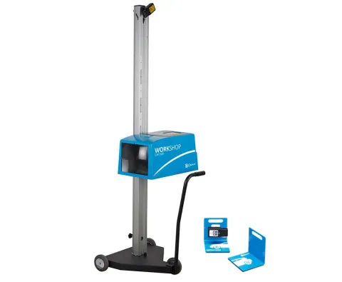
Headlight adjustment range

The headlight aimer requires a flat, unobstructed area in front of the vehicle, with a length and levelness determined by the specific device used. This area must be free of any storage items: this is often the space that is lacking in the facilities we take over.

See the headlight leveling tool lineup and our guide on how to choose a headlight leveling tool.

Emissions testing station

The emissions testing station requires a power supply, appropriate ventilation or exhaust system, and a location that allows access to the exhaust without obstructing traffic. The choice between separate and combined instruments directly affects the station’s footprint.

See our guide analyzer, opacimeter, or combined unit.

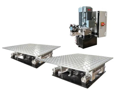
Sliding plates, play plates, and suspension test stands

This equipment is installed in the ground or in a pit, and its relative position determines the sequence of operations. Its layout is planned simultaneously with that of the brake test stand, with which it shares the civil engineering infrastructure.

Equipment that adapts to your facility

Compact designs, replacement adapters, and floor leveling: everything you need to simplify installation, whether setting up a new facility or retrofitting an existing one.

Why choose Capelec

Design office and factory together in Montpellier: you deal directly with the designer and manufacturer of your equipment, from design to maintenance. Equipment in use on every continent, with subsidiaries in Germany and India.

30+ years

designing and manufacturing measuring equipment

ISO 9001

certified production, every unit checked at the end of the line

10%

of revenue invested in research and development

48h

to receive a proposal tailored to your project

Checklist Before Requesting a Study

Gathering these items before the first meeting saves several weeks on a project.

  • Dimensioned floor plan of the facility, in digital format if possible.
  • Clear height and location of overhead obstacles.
  • Characteristics of the existing floor slab or foundation.
  • Available electrical power and location of the electrical panel.
  • Photos of the interior of the facility and access points.
  • Vehicle categories and expected traffic volume.
  • Desired opening or recommissioning date.

Submit my floor plan for review

Be careful with standard floor plans. A floor plan found online is not valid: it does not take into account your specific premises, the equipment you will use, or the requirements applicable to your business and market. A floor plan must always be validated on-site.

Frequently Asked Questions

What information should be provided for a site feasibility study?

The dimensioned floor plan of the facility, headroom and overhead obstacles, characteristics of the floor slab or foundation, available electrical power, photos of the interior and access points, target vehicle categories, and the desired opening date.

Can a testing line be installed in an existing facility?

Yes, provided that its dimensions, floor, access points, and utility lines allow for it. Several Capelec devices are designed to adapt to existing recesses and civil engineering features.

Who is responsible for the civil engineering work and utility connections?

The breakdown between civil engineering, utility connections, and equipment installation is determined during the project design phase and then formalized in the proposal. It depends on the site configuration and the progress of the work.

Is a standard layout diagram sufficient?

No. An installation is always validated on-site, taking into account the premises, the selected equipment, and the requirements applicable to your business and your market.

Continue

Have the layout of your inspection line evaluated

Send us a floor plan of your facility and the details of your project: we’ll let you know which configurations are feasible and what prerequisites you’ll need to prepare.

Back to top